INDUSTRIAL INVERTER (VFD)
Industrial inverter
Industrial Inverter (VFD)
What is Industrial inverter?
The ARB 150+ inverter is a high reliable genera; purpose drove delivering best motor performance with minimal hardware complexity and nil programming requirements.
General features:
- Three phase sinusoidal wave generation with DC bus ripple cancellation.
- Automatic motor voltage regulation against power grid fluctuations.
- Digital signal processing and loaded motor speed drop compensation.
- Thermal over – load protection of the motor with 150% current capability.
- Drive over – temperature protection at (65 C) and cooling fans monitoring.
- Automatic display of the motor current and frequency on the remote panel.
- Over – voltage protection at regeneration or at grid voltages above 440 Volts.
- Under – voltage protection at grid voltages below 330 Volts.
- Input phase loss protection to prevent unbalance and capacitor heating.
- Short circuit withstand capability weather line-line or line-earth in 10μs.
- Automatic controlled deceleration to prevent charge build up and over volts.
- Harsh environments working capability due to con-formal coating of the electronic boards.
Protective features:
- Uv this indicates that main input voltage has gone below 330 Volts, even if this happens temporary, the drive will cause the motor to stop.
- Ov this indicates that main input voltage has gone over 440 Volts, even if this happens temporary, the drive will also cause the motor to stop.
- br a high voltage less than causing OV condition will cause this error to be displayed along with resistive breaking to be activated.
- PL phase loss detection of drive input will cause it to stop, another reason for this will be when one of the cooling fans gets jammed or defected so PL watches over fans health as well.
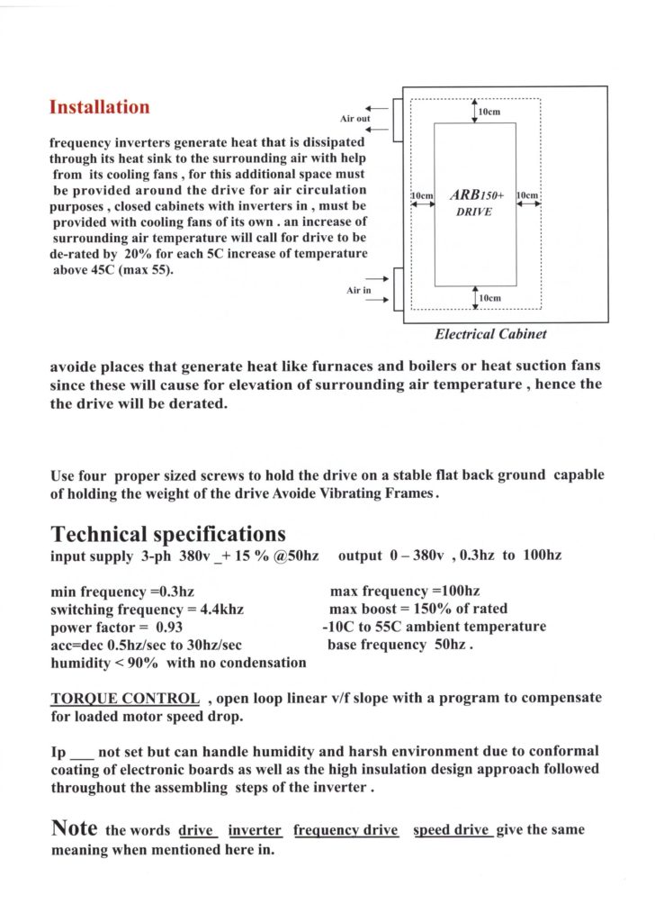
- OH over heat will cause the motor to stop if drive heat sink temperature is around 65c this might be caused by improper installation such as closed small cabinets that effect air flow.
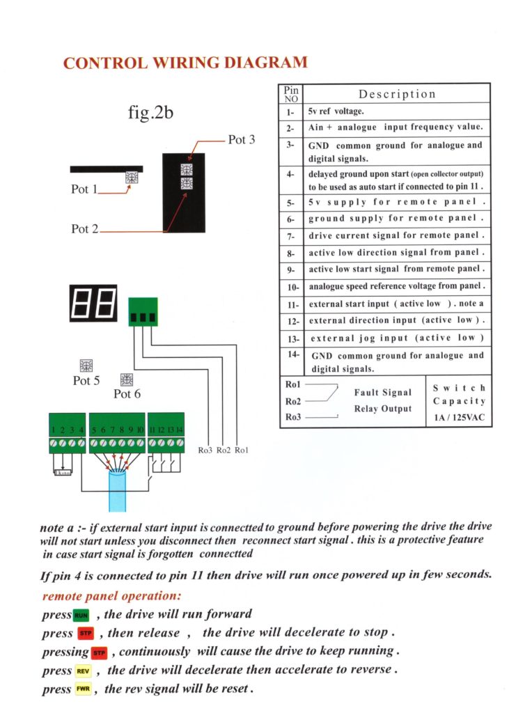
- rh this error is displayed if frequency reference analog signal corresponds to frequency above 100hz.
- OL this resembles the conventional thermal overload relay used to protect motors once motor current exceeds a level set by OC/OL potentiometer count down timer is initiated, the time initiated is proportional to the difference between the two levels.
- Oc this signal will cause the motor to stop and shutdown power in 14 microseconds. this occurs once motor current exceeds a level set by OC/OL potentiometer, a line-line or line-ground fault (short circuit) error will activate this signal.
Installation User Manual


